WELCOME!

It is hard to believe that it was almost ten years ago I witnessed a CNC router in action for the very first time. I was fascinated and simply had to have one! Although I had been in the creative end of the three dimensional sign business for most of my life I didn't really know what I would do with one of these machines - but I just knew it could do fantastic stuff.

Along with the CNC router I discovered the wonderful material called Precision Board and the glues, primers and other companion products they offer. Since then we have gone through many tons of the material using it in most signs and projects we tackle. This journal will chronicle our many adventures both past, present and future. I'll talk from the perspective of someone who pushes these products to the creative limit on a daily basis. I'll be adding to the stories two or three times each week. -dan

Saturday, October 28, 2017

Monument sign start to finish - part two

With the lath in place it was time for a little concrete work. I mixed up the sand and Portland cent at a ratio of about four parts sand to one part cement powder. Then I troweled it onto the mesh. This takes some practice. I've been doing it for decades so this part went pretty fast.


To ensure the next coat of concrete stuck well I scratched up the surface of the first coat. We used a bonding agent as well but a mechanical bond is good insurance.


This coat of cement was allowed to cure overnight.


Since the stone was still on order I started in on the painting process. We use acrylic house paint in our shop. I applied there base coats of each colour, allowing it to dry in-between. Putting a large fan on the project speeds up this process a great deal.


I then applied a dark green glaze (the same colour as the border) to the sign and wiped it off with a rag to make the grain pop. The glaze stays in the deeper areas and wipes off the high areas of the grain. The areas around the letters was left a little darker to make the letters pop off the background.

Once the glaze was dry I painted the scrollwork a couple of coats of a lighter shade of green. At this point my supplier let me know the faux rock I had ordered wasn't available in a reasonable time. It was time for plan 'B'. I put another thick layer of concrete on the base and carved the rocks into it by hand.


The rock work was painted (there coats of acrylic paint) and then speckled with an undercoat gun using two colours of acrylic paint. Use low air pressure (about 20-25 lbs)with the speckles. The mortar joints between the rocks was painted on with grey paint.

O then applied an old based size on the letter and symbol and gilded the letters. The sign was now ready to deliver.

Friday, October 27, 2017

Monument sign start to finish - part 1

I often get asked to talk about a 'typical sign' and how we build them. The answer is most signs we build aren't typical. But they do follow a pattern. I decided to do a small series of posts on a more 'normal' kind of sign - the kind most sign shops might tackle. I'll cover it from start to finish.

This sign was for a chiropractor. He has just refurbished his building and wanted a new monument sign out front. The building was a historic farm house and looked pretty good. I based the first design on the photograph he provided. 


The rock work on the bottom of the sign was to be faux stone so I went to my supplier's website and downloaded the picture of the rock. I photoshopped this onto the drawing to illustrate how it would look.


My client liked my first design but decided he would rather have the chiropractor's symbol instead of the building picture. I found the vectors for that logo online.


The second design was approved by my client.


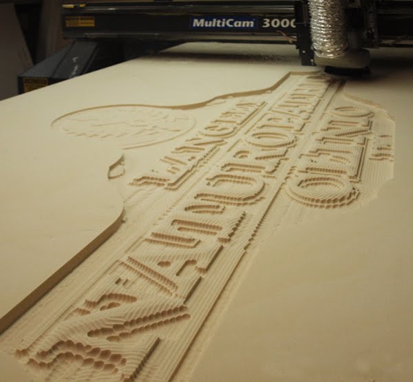
I designed the sign cutting files in EnRoute. The sign face was cut from 1.5" Precision Board which would be laminated to an additional six layers of 1" thick Precision Board. My client wanted a chunky sign!


Once the board was cut I fitted the 4" x 4" steel tubing into the cutouts and tacked up the frame.


I then finished the welding and added the base plates. I had asked my client to pour a concrete pad  six inches below the finished grade where the sign was going. This would allow us to simply lift the sign into position, drill some holes in the concrete, pound in some anchor bolts and tighten the nuts to do a quick and simple install. The stand would also allow me to work on the sign safely in the shop. Note the vertical bar which fit into the middle layer of the sign. This bar is the structure for lifting the sign. I welded a threaded nut to the top into which I twisted an anchor bolt. This was removed when the sign was placed onsite.


I then glued and screwed the layers of the sign together. Note how the one part urethane glue tends to bubble out as it cures. This can be wiped up as it squeezes out but we have a little different approach.


For the next stage we use an air powered die grinder to purposely add texture to the sides and back of the sign. This step also gets rid of that pesky glue. For some reason I timed how long it took me to do the texturing with the die grinder... it was thirteen minutes. I should note that when the good doctor came to approve his sign he walked around the sign admiring it. He ran his hand over the texture on the car and sides of the sign and asked me if I had done that by hand. I nodded. He then said 'It must have taken a LONG TIME!' I smiled and told him he had no idea how long it had taken me. He then happily wrote me the check, feeling good about the value I had put into the project.

I have no doubt that if I had sanded it perfectly smooth he wouldn't have mentioned it, simply assuming that machines had done the work. :)


The screw holes were filled in with epoxy putty... no sanding required as it blended into all that texture.


I then welded up a pencil rod frame. The wire lath would attach to this framework.


The galvanized lath comes in three weights... we use the medium weight. It is cut to size with the snips and a pair of end cutters is used to twist the rebar tie wire to fasten on the lath. The wire is bent into a hook and then inserted through the lath to hook around the pencil rod. It is then pulled back through the lath and twisted and cut flush with the surface. This job takes practice to get good and fast.


With the wire in place it is time to go to the next step... and I'll cover that next time. Stay tuned...

Friday, October 13, 2017

Building a mine car

I find it a great deal of fun to design rather complex designs and then figure out a way to fabricate what I have imagined. We are currently working on a good sized theme project called the Cloud Buster. It is a drop tower ride. The thing that separates this ride from all of the others is that the one hundred and twenty-five foot tower ride will be positioned on top of a seventeen foot tall concrete tower. Our job is to theme the concrete structure to fit into the adventure golf course below. I have chronicled the sign for this project previously on this journal. As with all of our projects it started with an idea and a concept drawing.

The concrete tower will be hidden by wrapping a portion of a mountain around it. A mine shaft will go through the centre and guests will be able to golf through this feature.

Construction of the theme work is now well underway. The tunnel through the structure is being fabricated in two sections. This will be lifted into the centre of the golf and then slid into place (no small feat). Then the six outer sections will be craned into place around the tower and bolted together. As with much of our work we will sculpt the rock and timbers from fibreglass reinforced concrete.


A mine car will be situated where guests enter the mine. It will add to the theme and also act as a number marker for the hole. Our client was inspecting the progress on the mine shaft early this week and noticed the work I had done on our rail car which was sitting in the shop parking lot. (Samples work!) He asked for his mine car to have the same kind of detail he saw on our rail truck. I did up a quick concept and he gave it the thumbs up!


I designed the car totally in EnRoute. Everything would be created from steel which meant our MultiCam plasma cutter was going to get quite a workout. The pieces were cut from 1/4" and 1/8" plate steel. I allowed three days to design, cut and fabricate the mine car. I did all of the fabrication by myself, save for when I needed some lifting assistance. I managed to do it all in about twenty hours of work.


By quitting time today the fabrication was complete. We'll sculpt the rocks in the car and the base using fibreglass reinforced concrete. The car will be allowed to rust to make it look old.


Tuesday, October 10, 2017

Tank Details

The wind up key mount was the first accessory relief to be created for the tank. I started with a flat relief 0.2" tall.


The rivets were the next modification by using the dome tool.


The centre was the next step, also created with the dome tool and the add to command. 


In order the take the guess work out of where to drill the hole for the key I added a digit to the centre using the dome tool with the take away command.


Next up was the hatch lid. It started as a simple flat relief.


This flat relief was modified using the dome tool


The two mountain g arms were created as 1/2" tall flat reliefs.


These two arms were then combined with the lid of the hatch.


The hatch itself was the next step/. It was created as a flat relief which was 0.2" tall.


The raised ring and lid mounting flange vectors were then used to modify the flat relief using the add to command. They were raised 0.8" making the piece a total of 1" tall (the same thickness as our board)


The last step was to add the rivets using the dome tool.


That finished the reliefs for the tank. It was a simple matter of tool pathing them and sending the files along to the MultiCam to be cut from 30 lb Precision Board.