WELCOME!

It is hard to believe that it was almost ten years ago I witnessed a CNC router in action for the very first time. I was fascinated and simply had to have one! Although I had been in the creative end of the three dimensional sign business for most of my life I didn't really know what I would do with one of these machines - but I just knew it could do fantastic stuff.

Along with the CNC router I discovered the wonderful material called Precision Board and the glues, primers and other companion products they offer. Since then we have gone through many tons of the material using it in most signs and projects we tackle. This journal will chronicle our many adventures both past, present and future. I'll talk from the perspective of someone who pushes these products to the creative limit on a daily basis. I'll be adding to the stories two or three times each week. -dan

Saturday, November 28, 2015

Trade show booth - part one

We have decided to take part in next years expo hosted by the International Association of Amusement Parks and Attractions. It is no small investment to take part as a vendor and so we want to make sure we go all out. After giving it a lot of thought we have decided to create a small studio there showcasing the best of our many samples. We'll also play our videos and have hand out materials. As we thought about transporting everything down and setting up we decided to build a giant box with a canvas cover. It will be a simple matter of placing it in the booth, taking off the cover and with a little rearranging be ready for the show. The box needs to be part of the display of course and display the same magic we create on a daily basis. The new MultiCam Plasma cutter will play a large part in it's construction as will the router. Peter and I designed the booth this past week.


Then it was time to begin cutting some steel. Since we won't be present when the trade show staff unloads and handles our booth we knew we had to make it foolproof and extra sturdy. We designed forklift pockets that go through the booth floor in both directions, making it possible to lift it safely from any side. The primary steel tubing frame measures  4" x 8".  


I designed the vectors for the plasma cutter in EnRoute and then cut them from 3/8" plate steel.Stay tuned for progress reports as this thing comes together.


I then began fabrication by welding the pieces into position. 6" x 3/8 flat bar will be welded to the edges to form I-beams


Tuesday, November 24, 2015

Train model done

Today Jenessa glued on the last small bits and and painted on the last brush strokes to finish both train models. They look spectacular! As soon as we get the final measurements from the train chassis builder we will start in on the full size version.


Saturday, November 21, 2015

Arms and legs

Each time I get a few minutes I add more pieces to the Sign Challenge piece. It is largely hand sculpting at this point. The latest additions are the rocket legs and the rocket engine.


The piece is a parody of the sign making industry and makes commentary on two long standing issues. The first is the old time 'snapper'. This itinerant sign painter would travel from town to town and snap up the good jobs, much to the chagrin of the local tradesmen. Our sign maker is such a worker, only he travels from planet to planet. He also uses the latest computerized sign making equipment, the boon of all old school sign makers in the galaxy. 

Tuesday, November 17, 2015

Starting the sculpt of the vehicles

Once the accurately routed vehicle forms are securely anchored in place, it is relatively easy and quick to apply  thin coat of sculpting epoxy and sculpt in the fine details. The character armatures are first built from twisted wire, over which I press on a little sculpting epoxy to form the basic shape. Once cured a final layer is again pressed on and the details are sculpted in.

The motor cycle was first along with the form for the girl hanging on the back. I roughed her out first and then after she was complete moved to the fellow driving.


The delivery van was next on the agenda.


In the final two pictures we can see clearly how the pieces are quickly coming together and how everything relates to each other. It is a tight envelope to work in! The rocket in the middle will be the next section to be sculpted as access to that area is getting tougher as things proceed.


Saturday, November 14, 2015

Building the vehicles - part four

When we left off the vehicle was looking pretty good but now it was time to start in on the customization to make four different vehicles.


The vehicles would be a pickup, a long flatbed truck and a short flatbed cab over. Behind the bar were three round corner rectangles. I selected them and made them into a 1" tall relief.


For the pickup I stretched it vertically to just below the convertible cab.


Then I used the subtract tool to make a hole in the box and in the process a floor for the bed of the pickup.


For the cab-over (Stubby nose truck) I didn't stretch the back vertically as much.


 For the last truck I stretched the back vertically so it became the box for a delivery van.


For the motorcycle I first shortened the width of the base. Then I created two vectors - an oval and the other a sort of egg shape. The headlight is one off of the other vehicles. These were made into a relief using the dome tool.


The seat was also created using the dome tool.


I combined the two reliefs then nudged the seat into position vertically.


Then I merged highest.


I now had four vehicles .


 The vehicles next needed to be sliced vertically and EnRoute Slice tool made the job easy!


The slices were arranged and then sent off to the MultiCam to be routed from 1" thick 30 lb Precision Board.


After they were routed I stacked up the test pieces for a look. (the center car was a test piece done previously)

Friday, November 13, 2015

Building the vehicles - part three


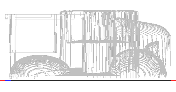
One of the things I love about EnRoute is how I can combine all kinds of shapes to form anything I can imagine. Sometimes it is a matter of adding things together and sometimes it is about taking things away. By changing things up just a little I can modify the shapes and change them at will to make something different.

On the vehicles I started with the headlights.  The first step was a simple oval using the dome tool.

I then clipped off the front by merging lowest with a zero height rectangle.


I used the slice tool to get rid of the flat bits.


The running boards were created using the dome tool with a shallow edge on the relief.


The front and rear fenders again were formed using the dome tool and a steeper angle.


I then nudged the headlights up to where they needed to be in the side view.


The rest of the fenders were then completed.


The dome tool was again used to create the hood on all of the vehicles.


Then everything except the headlights was combined. The headlights were merged (highest) with the combined relief.


The cockpit relief was next, once again created using the dome tool.

Wednesday, November 11, 2015

Building the vehicles - part two

The bodies of the car were both a great deal of fun and also very challenging. I had to imagine all of the different shaped building blocks which would form the various body panels. I first created the vectors for half of the vehicles, duplicated, flipped and aligned before combining them. In the first screen capture we see the front and rear fenders, the passenger cab and the hood of the little truck The square shape will form the box of the pickup. The outside oval , which is the chassis base was only used to guide my sizing of the vehicle.


I then used the offset tool to create the vectors I needed to shape the inside of the cab and ox of the pickup.


That's how the first vehicle vectors were created. The other vehicles used many of these same pieces.